PULL OUT CAPACITY TEST
September 5, 1996
Revised September 17, 1996
Steve Ross
Foam Concepts
825 Lakeview, Unit C
Placentia, CA 92670
Re: Lab. No 10678-96/1433
Dear Steve:
At your request, Ramtech Laboratories conducted testing to determine
the following:
A. Determine the pull out capacity of the Styro-loc metal insert
from Type I Expanded Polystyrene Foam.
B. Determine the capacity of the metal flashing, flashing strip and
STYRO-loc®
system when subjected to negative loading.
The Styro-loc system incorporates a 0.025-inch thick metal insert which
is inserted into a slot provided in the Expanded Polystyrene Foam. See
Attachment 2 for detail.
The metal insert may be placed at any location on the surface of he
EPS. The assemblies submitted to the laboratory had the insert placed
2.62 inch from the edge. For design of parapets to include decorative
designs, the EPS is molded to various shapes and adhered to the face
of the parapets. To facilitate the attachment of the flashings to cover
the top, the Styro-loc insert provides a method to anchor the flashing
to protect the top of the EPS and parapet.
Test
Specimen:
The test specimens, delivered to Ramtech Laboratories, were 18 inches
wide by 48 inches long by 12 inches thick. The metal inserts were located
approximately 2-5/8 inches from the edge of the EPS. A 2-inch wide metal
strip/clip of 0.056 inch thick metal, including galvanizing, was installed
perpendicular to the Styro-loc inserts at 23 inches centers. The metal
strip was bent around the edge and extended down 3 inches. The end of
the metal strip/clip was bent outwards approximately 1/2 inch to receive
the flashing. At each intersection with the Styro-loc inserts, the metal
strip was fastened to the Styro-loc insert with one hex head self drilling
screw (0.125-inch shank x 7/8-inch long). See Attachment
1 for manufacturer’s brochure.
-----------------------------------------------------------------------------------------------------------------------------
Test Program:
A. Negative Uniform Load Test: For this test, the flashing
cap was loaded using an air bag. The air bag was placed between the
flashing cap and the EPS foam. Air was introduced to the air bag using
a compressor and the resulting pressure was monitored with a water manometer.
Dial indicators were located at the edges of each strip/clip location
and at the midpoint. Pressure was increased at _ inch water column (2.6
psf) with rebound to zero pressure after 3 and 6 inches water column.
B. Pull out Capacity of Metal Insert: This test was conducted
to determine the pull resistance of the metal insert form the EPS foam.
A self drilling screw was installed at 1 inch from the end and 24 inches
from the end. In addition, pull tests were conducted to determine at
what edge distance the full pull out value can be achieved.
GUIDELINE
DIAGRAM
Results:
A. Negative Uniform Load Test: The three negative Uniform
Load Test failed by bending failure of the metal strip/clip. The metal
strip is located at the edge and at the midpoint of the assembly. The
failure in all cases was by bending of the strip at the screw location.
Results of the Negative Uniform Load Test are summarized in Table A.
B. Pull Out Capacity of Metal Insert: A self drilling
screw was installed at the location specified. The screw was pulled
directly in tension until the EPS foam failed. The results are summarized
in Table B.
Analysis of Results:
The results indicate that the metal strip/clip yielding will limit the
design as tested. The metal strip/clip bends about the screw attachment
to the Styro-loc insert. The allowable load, based on the total surface
width of 18 inches and the metal strip/clip spaced at 23 inches centers,
is 6 inches of water or 31.2 pounds per square feet. This load causes
the metal strip/clip to yield. The maximum pull out value for the Styro-loc
insert is 227 pounds when loaded a minimum of 12 inches from any end.
The load, when pulled at 1-inch from the end, averaged 88 pounds. The
Styro-loc insert is located a minimum of 2-5/8 inches from the edge
of the EPS foam. The EPS foam must be listed and be manufactured under
a quality control program using a third party inspection agency.
| TABLE
A |
Water |
Load |
Test
1 |
Test
2 |
Test
3 |
Column |
(psf) |
Ave.
1&2 |
Ave.
3&5 |
Ave.
6&7 |
4 |
Ave.
1&2 |
Ave.
3&5 |
Ave.
6&7 |
4 |
Ave.
1&2 |
Ave.
3&5 |
Ave.
6&7 |
4 |
0.5 |
2.6 |
0 |
0.001 |
0 |
0 |
0 |
0 |
0 |
0 |
0 |
0 |
0 |
0 |
1 |
5.2 |
0.007 |
0.001 |
0.002 |
0.015 |
0.004 |
0.002 |
0.006 |
0.036 |
0.001 |
0.002 |
0.003 |
0.081 |
1.5 |
7.8 |
0.013 |
0.007 |
0.009 |
0.118 |
0.009 |
0.005 |
0.009 |
0.112 |
0.001 |
0.005 |
0.006 |
0.250 |
2 |
10.4 |
0.017 |
0.011 |
0.012 |
0.136 |
0.016 |
0.009 |
0.013 |
0.187 |
0.009 |
0.009 |
0.013 |
0.345 |
2.5 |
13 |
0.028 |
0.021 |
0.017 |
0.258 |
0.022 |
0.012 |
0.017 |
0.247 |
0.018 |
0.012 |
0.018 |
0.400 |
3 |
15.6 |
0.043 |
0.033 |
0.021 |
0.376 |
0.032 |
0.019 |
0.023 |
0.415 |
0.028 |
0.019 |
0.023 |
0.450 |
0.5 |
2.6 |
0.005 |
0.003 |
0.004 |
0.008 |
0.002 |
0.004 |
0.008 |
0.021 |
0.003 |
0.004 |
0.002 |
0.090 |
3 |
15.6 |
0.043 |
0.031 |
0.022 |
0.375 |
0.031 |
0.019 |
0.023 |
0.410 |
0.030 |
0.019 |
0.025 |
0.466 |
3.5 |
18.2 |
0.048 |
0.040 |
0.025 |
0.489 |
0.039 |
0.028 |
0.028 |
0.460 |
0.040 |
0.028 |
0.032 |
0.512 |
4 |
20.8 |
0.064 |
0.057 |
0.035 |
0.510 |
0.051 |
0.037 |
0.036 |
0.514 |
0.052 |
0.037 |
0.040 |
0.560 |
4.5 |
23.4 |
0.080 |
0.073 |
0.051 |
0.545 |
0.063 |
0.047 |
0.044 |
0.558 |
0.054 |
0.047 |
0.049 |
0.605 |
5 |
26 |
0.103 |
0.084 |
0.065 |
0.690 |
0.079 |
0.065 |
0.060 |
0.628 |
0.082 |
0.065 |
0.068 |
0.670 |
5.5 |
28.6 |
0.122 |
0.121 |
0.080 |
0.750 |
0.100 |
0.081 |
0.068 |
0.670 |
0.088 |
0.081 |
0.068 |
0.690 |
6 |
31.2 |
0.152 |
0.135 |
0.033 |
0.810 |
0.121 |
0.098 |
0.075 |
0.715 |
0.096 |
0.098 |
0.082 |
0.720 |
0.5 |
2.6 |
0.010 |
0.015 |
0.009 |
0.052 |
0.006 |
0.011 |
0.013 |
0.045 |
0.016 |
0.011 |
0.015 |
0.270 |
6 |
31.2 |
0.153 |
0.139 |
0.099 |
0.815 |
0.148 |
0.122 |
0.103 |
0.750 |
0.095 |
0.122 |
0.091 |
0.750 |
7 |
36.4 |
|
|
|
1.065 |
|
|
|
1.001 |
|
|
|
|
8 |
41.6 |
|
|
|
1.615 |
|
|
|
1.251 |
|
|
|
|
9 |
46.8 |
|
|
|
1.565 |
|
|
|
1.501 |
|
|
|
|
10 |
52 |
|
|
|
1.815 |
|
|
|
1.751 |
|
|
|
|
11 |
57.2 |
|
|
|
|
|
|
|
|
|
|
|
|
Ultimate |
11.5"
= 59.8 |
11"
= 57.2
|
11.5"
= 59.8 |
Average |
|
59
|
|
TABLE
B
Load in (Pounds) |
Test
No |
Load Applied
1" From End |
Load
Applied
24" From Each End |
Load
Applied
4" From End |
Load
Applied
8" From End |
Load
Applied
12" From End |
1 |
88 |
235 |
135 |
|
|
2 |
86 |
222 |
|
187 |
|
3 |
90 |
225 |
|
|
218
(1) |
Average |
88 |
227 |
|
|
|
Mode
of Failure |
Insert
Peeled Back Foam |
Foam
Sheared |
Insert
Peeled Back Foam |
Insert
Peeled Back Foam |
Foam
Sheared |
| Connection
to the Styro-loc inset must be a minimum of 12 inches from the free
end to develop full pull out of capacity. Appropriate safety factor
should be applied to the peak value to determine allowable design
value. |
GUIDELINE
DIAGRAM
TYPICAL
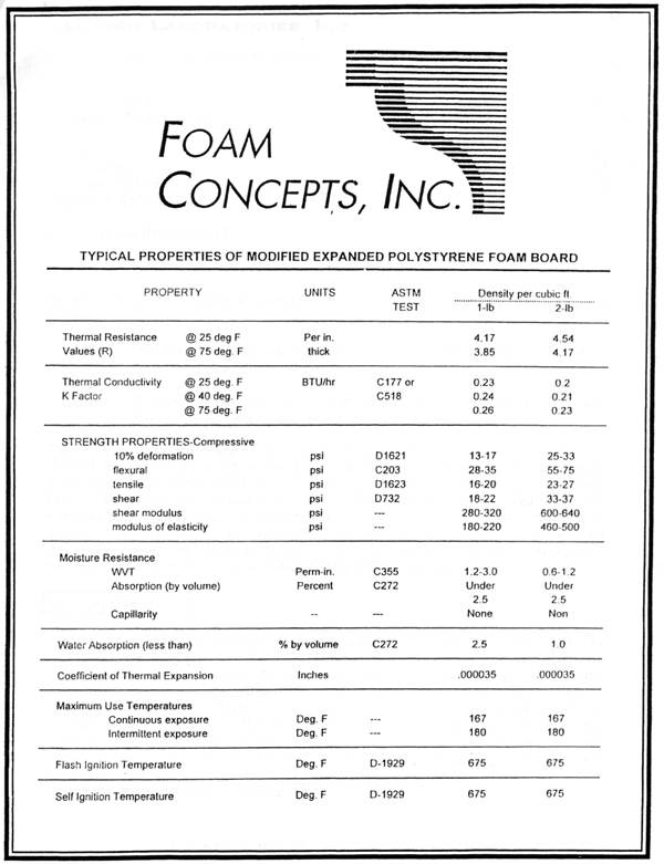
PROPERTIES OF MODIFIED EXPANDED POLYSTYRENE FOAM BOARD
-----------------------------------------------------------------------------------------------------------
Please give us a call if you have any questions.
Tested by:
Steve Berggren
Laboratory Supervisor
Reported by:
Ronald I. Ogawa, P.E.
Laboratory Consultant
Report
Reviewed and Approved by:
David R. Macey
Laboratory Manager
RAMTECH LABORATORIES, INC.
14104 ORANGE AVENUE, PARAMOUNT, CALIFORNIA 90723 • TEL (310) 633-4824
• FAX (310) 633-4128

